Tuesday, July 27, 2021

HS Produkt VHS-2 Airsoft Replica Build [Part 3: Grip and Fire Controls]

Okay, so now we get to a real pain in the ass part of this build: the grip, trigger, and fire selector.

 
The grip and fire controls are comprised of the following parts:
  • Grip (housing)
  • Trigger
  • Trigger PCB button
  • Trigger switch mount
  • Trigger spring
  • Rotary potentiometer
  • Rack
  • Pinion x2
As you may have figured out from that list, the trigger just activates a PCB button. The real meat and potatoes of this fire control group is the fire selector. We're spinning a rotary potentiometer to select the firing mode, but this introduces challenges. 

Namely, I can't just hook up a potentiometer to the selector switches themselves. This would employ two potentiometers that are not synchronized (one for each half). There are rotary pots that allow a keyed shaft through the center, but this requires more machining than I'm capable of doing with my current setup. 

The solution, of course, is a rack-and-pinion:

Imagine another pinion sitting between the trigger and that pinion on the potentiometer. This translates the rotation from the fire selector downwind to the potentiometer, allowing an Arduino to pick up the position. Also imagine a PCB switch on that little shelf in front of the trigger - that translates trigger movement into a readable position as well. Clever, huh? Big shoutout to janssen86 on Thingiverse for the parametric helical rack and pinion model he made, though I did modify the hell out of it to fit in the grip and to not be helical. 

I printed the rack and pinion out of Dr.3D ABS-like resin, which I have been VERY impressed for at the price (it costs about as much as normal UV resin, but comes in 500g bottles instead of 1kg).


That's it for the grip and fire controls. Took far too much effort, too many re-prints of tiny resin parts. See you next time for the lower receiver. Worth noting, there will possibly be a significant amount of time before the lower receiver part is published - I have to do more test fitting prints, which means more hours into printing parts destined for the garbage can. I have queued posts to release once per week to prevent this from being too bad, but if you're keeping up with the project, just be aware.

-Craig, ETW

HS Produkt VHS-K2 Airsoft Replica Build [Part 2: Upper Receiver]

Alright, with the barrel assembly done, now it's time to do the rest of the upper receiver.

I split the upper receiver into four parts due to the size - two for the top rail, two for the actual upper receiver body. 

The longest piece of this assembly is 300mm. This would unfortunately end up being slightly tool tall to print on the Ender 3, so I had to take... action:

I also have a Creality CR-10S5, which is an absolutely enormous printer - so enormous that it prints everything poorly unless I have it print at a snail's pace even after hundreds of dollars of upgrades, so it's mothballed. I decided to take the Z axis extrusions and lead screw off to put on the Ender 3. The E3 can't travel all the way up the new Z axis due to the cable loom length, but I'll make an extension later. It's long enough for this part, at least.

Printing the rear receiver half was much simpler, as it's only around 150mm long.

The extension to the chamber block is now serving part of its purpose - to affix the rear end of the barrel assembly to the upper receiver using two M3x8 screws. There is a slight protrusion on the back to lock the upper into the lower - more on that later.


And there it is, the upper receiver all printed. The gap between the two rail sections is an unfortunate result of stacking tolerances - luckily, these aren't critical, but I will probably end up replacing the top rail with an adjusted version later. I haven't started the charging handle yet because I may be having part of it machined out of aluminum for me, as 3D printed options for the "knuckle" will probably end up being too fragile long-term.


So yeah, upper receiver's all done. On to the grip and fire control group. Next time!


-Craig, ETW


Tuesday, June 29, 2021

HS Produkt VHS-2K Airsoft Replica Build [Part 1: Barrel Assembly / Mock Gas System]


This is the barrel assembly and mock gas system for the VHS-2K. Everything pictured in silver is going to be a metal component - most parts will be aluminum for ease of machining on my very basic lathe setup, but the springs and spring shafts will be steel.

Each of the featured parts has a specific name. Familiarizing you with all of them would be quite a pain in this format, so for the sake of brevity, here's just the names of the relevant parts, front to back:

  1. Gas block adjustment knob (PLA+)
  2. Gas block (PLA+)
  3. Accumulator (Aluminum: 12mmOD, 10mmID)
  4. Forward interface (PLA+)
  5. Piston (Aluminum - 10mmOD, 3mmID)
  6. Charging handle interface (PLA+)
  7. Charging handle spring guide (x2) (HSS)
  8. Charging handle spring (x2) (Steel)
  9. Chamber (PLA+)
  10. Chamber extension (PLA+)

The majority of these parts exist so the charging handle can be pulled and not break something. I also wanted the charging handle to feel substantial when you pull it and wanted to try to use this assembly to counterbalance the relatively hefty FAMAS gearbox, hence making a lot of it out of aluminum and steel rather than just plastic.

In order to successfully mount the gas block in such a way where it would key to the outer barrel, I needed to print a jig to guide a drill bit so I could easily cut out just a small amount of material perfectly aligned with the top of the barrel key in the rear. Luckily, from the host replica's gas block, there were two divots in the bottom of the barrel I could use as keys.


The damage to the jig was planned - it was made a very tight fit so it wouldn't rotate easily while drilling, so removing it damaged it a bit. The drill bit unfortunately walked very slightly on the front cut, but the visible offset is mostly just surface-level and doesn't affect anything.

With that done, it's finally time to start printing and machining parts.

One, two... skip a few...


Machining the "piston" SUCKED because the only tooling I have for my crappy little lathe is a single cutoff tool and a dull HSS cutting tool. Took me around 2 hours to get it done as a result, taking away a hair's width of aluminum at a time... but it's done now. Later I will probably buy some cheap tooling to do a finishing pass and then give it a mirror finish with some sanding pads and buffing compound. Totally fine for now, though.

I initially designed some clips to go on the front of the spring guide rods to retain the charging handle interface and the springs, but realized as I was assembling everything that they weren't necessary. The only retaining clip I wound up keeping was on the rear of the charging handle interface (dead center in the second picture) - and that's just to allow the charging handle to actually pull the piston rod back.

I used aluminum pin stock to make the indexing/fixing pins for each of the parts that needed them - here's the gas block for example. I cut them with a band saw and added chamfers by chucking them in my drill press and raking them with a file. Didn't need to be exact, just needed to easily slip into the holes and not get caught up on anything.


And that's all there is for the barrel assembly and mock gas system. All things considered, this went together really easily, and I'm quite happy with the end result. In the next part, we'll get started on the upper receiver and fitting the barrel assembly into it.
 
-Craig, ETW

Wednesday, June 23, 2021

HS Produkt VHS-K2 Airsoft Replica Build [Part 0: Introduction]

This is the HS Produkt VHS-2.


Often seen in video games looking for an exotic, "sci-fi"-looking assault rifle that actually exists somewhere. Allegedly, the Croatian military uses these.

Have you ever seen The Fly with Jeff Goldblum? Basic synopsis: Man creates teleportation machine. Fly sneaks in on accident when he teleports, and he comes out the other end having been turned into a horrifying fly-man monster. Now replace Jeff Goldblum with a FAMAS, and the fly with every noteworthy polymer rifle ever designed, and you have the VHS-2. It is a short-stroke piston bullpup rifle that gets very very hot when you shoot it. The controls are fully ambidextrous, and almost everything about what it looks like on the inside is a complete fucking mystery for some reason.

I never really noticed the VHS-2 until using it heavily in Insurgency: Sandstorm, and slowly over time I've come to love the design

Unfortunately, as it is in the airsoft industry, nothing's being made unless it's an M4, AK, or some other incredibly popular weapons platform that has every right to dominate any related industry it finds itself in. Until the VHS-2 somehow ends up in a popular movie or video game title, it'll probably never find a spot in the airsoft industry.


That's why people like me exist, I suppose.


Visually capable individuals will note the "belly" on the stock, which has replaced the forward assist and length of pull adjustment. This was necessary to fit the V1.2 FAMAS gearbox. 

I initially began the process by searching for a model I could simply modify into a functional chassis, but quickly realized that the only free, publicly-available VHS-2 models were either very low poly or had design inaccuracies in the worst possible places to have them... so I started making my own, from scratch.

Now, this isn't the HCC-2A project from years back, and I'm not the inefficient modeller that I used to be. This was no year-long journey of introspection to learn how to extrude a box and use boolean modifiers. I went from absolutely nothing to nearly done in about 10 hours of work spread over a week in my down time. There's still minor details left to go - charging handle, dust cover, and mock bolt are the big ones - but the bulk of the work is done now.

Of course, I haven't said a word about the insides yet.

 
The boring stuff: it'll use a 14.5" M4 outer barrel, a 363mm inner barrel, and a G36 magazine (the G36 magazine is so close to the VHS-2 mag that I really don't see a purpose in making my own magazines).
 
Because I hate myself, rather than just making this an HPA engine chassis, I've decided to make it an AEG.
 
 
Eternally lauded as a complete and utter nightmare, this is the gearbox out of a FAMAS. This gearbox design first piqued my interest years ago as a potential candidate for strange rifle designs. The key factor for the Cybergun version of this gearbox that plays in its favor is that it is not a typical V1 gearbox - the piston, spring guideand gears are standard V2 style, the spring guide seems to be V3, and the motor is a standard short-type motor. The cylinder head is a V7 (M14), and the air nozzle is P90 type. The only proprietary parts in the gearbox are the trigger contacts, cutoff lever, and gearbox shell itself. That is to say, for all intents and purposes, this gearbox is fully upgradeable - a significant advantage over the standard V1 gearbox.

Here's where the challenge comes in.

For my VHS-2 project, I do not want a mechanical trigger linkage. I have owned airsoft bullpups before, and these universally suck. I want a trigger that doesn't feel like I'm about to break something every time I pull it, and to accomplish that, I'll have to get creative. I need the gearbox to not only cycle the gearbox only one time on a semi-automatic trigger pull, but I also need it to enforce cycle completion - to force the gun to cycle at least one time no matter how long the trigger is pulled - on every shot in semi-automatic. I can easily wire a microswitch or PCB button in front of the trigger, but how do I moderate gearbox operation in semi-automatic if I can't use the cutoff lever?
 
 
This is a Hall effect sensor. Hall effect sensors detect magnetic fields and blah blah blah. Why is this important? The Hall effect sensor isn't useful by itself. But connected to an Arduino running just the right code, and this thing will report every single time the sector gear moves. Using this, I can instruct the Arduino to close a MOSFET every time the trigger is pulled, and to not stop sending voltage until the Hall effect sensor is triggered to a certain degree. 

Hall effect sensors can report very quickly - this little guy will report up to 10KHz. That's a polling rate equivalent to reporting the sector gear status 10,000 times per second. Match that with an Arduino that operates at 16MHz, and we easily have the ability to read every single time the sector gear rotates. Using this principle, it's very simple to throw together a script that instructs the Arduino to act as we want it to. 
 
We are essentially building the world's most space-inefficient GATE Titan. All to avoid a crappy trigger. 

And that's pretty much the outline for the project. In the formal Part 1, I'll be assembling the "gas system", as it's the only assembly I have all the parts modelled to their final iterations so far. 

See you then.
-Craig, ETW


Sunday, October 25, 2020

CR-10 S5: The 10 Most Useful Modifications

If you've seen pretty much anything I've ever posted here, you'll know that I own a CR-10 S5. Since the first day I purchased it nearly two years ago, there's been a non-stop flow of modifications going in and out of the printer to try to optimize print quality - with the S5 absolutely exceeding the mechanical design considerations of the Cartesian format, there is something inherently Sisyphesian to the task. 


After all my time, effort and money, I've compiled a list of ABSOLUTELY ESSENTIAL MODIFICATIONS for the CR-10 S5.


01. ANTCLabs BL-Touch

In my opinion, the BL-Touch (or other automatic bed leveling probe) is an absolute must-have for ANY Cartesian 3D printer. With some simple firmware adjustments in Marlin and Klipper, you can say goodbye to bed leveling screws FOREVER. Manually adjusting your bed screws and doing paper tests on the nozzle become a thing of the past, and on huge printers like the S5, the benefits cannot be overstated. You can buy one here! Note: the metal probe tip featured in the above image was phased out several generations ago in favor of an engineered plastic which has a far longer lifespan.


02. Keenovo Silicon AC Bed Heater

While I'm not particularly spiritual, it is said that God works in mysterious ways. So too do the engineers at Creality, whom decided a 300mm DC bed heater was sufficient for a printer with a 500mm bed plate. If you've owned any 3D printer, you've encountered the limitations of DC heaters only just barely making it to 80C at best, and even then, taking as long as 10 minutes to do so. With a Keenovo AC bed heater, you can push your bed as hot as 260C (please don't do this!) in mere minutes - seconds, even, for common printing temperatures from 60C-110C. The downside is that integrating a Keenovo AC heater to your 3D printer's mainboard may prove difficult depending on the mainboard infrastructure. However, after thousands and thousands of printing hours, I've found having to turn the bed heater on and off to not be much of an annoyance. It also prevents inter-print cooldown of the bed - once you finish a batch of ABS parts, you don't have to wait for the bed to heat back up, it's just ready immediately. The control box for the Keenovo bed heater is also incredibly simple to use, so you won't be endlessly scrolling through menus trying to find the setting you need. You can find these easily on Amazon, eBay, and Aliexpress, but make sure that it's the right size for your bed and has pass-through holes for the bed screws pre-installed! You CANNOT safely drill into these blindly!


03. Diagonal Frame Reinforcements

These are struts that run diagonally from the front of the printer's lower frame to the top of the Z axis struts. These dramatically decrease the Z-axis wobble on taller prints, which are a serious problem when the bed is flopping around like crazy 30 hours into a 50 hour print. While some commercially-available kits work, I made mine using 5/8th" threaded rods, nuts, washers, some 3D printed brackets, and some post-assembly M4 T-nuts.


04. TL Smoothers

All Creality printers have an inherent problem of using A4988 stepper drivers by default. While these little guys are legendary and widely-proliferated for a reason, they unfortunately result in the "salmon skinning" effect that is infamous among Creality machine owners. TL Smoothers are a cheap and easy modification to put in line between the steppers and stepper drivers, and will completely (or mostly, anyway) remove the salmon skinning effect. You can buy a set here! However, if you want a less cumbersome option that comes with the added benefit of reducing the "robot noises" your printer makes while printing...


05. Creality V1.1.5 Mainboard (with TMC2208 stepper drivers!)

This is a full replacement for the factory mainboard. It comes equipped with TMC2208 stepper drivers. While Creality uses this as a marketing point for a more silent printer, this also significantly reduced artifacts caused by the A4988 stepper drivers, removing the need for TL Smoothers entirely. Unfortunately, this mainboard tends to come in and out of stock everywhere I've found it rapidly, so just keep an eye out for a Creality V1.1.5 mainboard with 2208 stepper drivers! The only real downside of this mainboard is that you lose the independent pin headers for each of the two Z-steppers, but you can easily wire up a splitter, which works fine! Note: This board requires a 24v power supply. Which leads me to the next point...


06. Meanwell 24v Power Supply 

By replacing just a handful of fans, your mainboard, and your heater cartridge, you can convert your CR-10 S5 to 24v. This gets your hotend up to printing temperature faster, runs the steppers cooler, and allows you to use the previously-mentioned V1.1.5 mainboard. It's worth it! Believe me! You can buy one here!


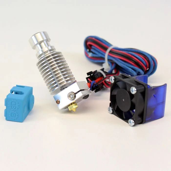
07. E3D V6 All-Metal Hotend


Unfortunately, all standard Creality printers come with partially-metal hotends. This means there's a PTFE liner inside of your hotend, and if you raise the hotend temperature to ABS temperatures, you risk vaporizing the PTFE liner. This is incredibly dangerous, so if you want to print materials like ABS, PETG, and Nylon reliably and safely, getting an all-metal hotend is a GREAT idea! To be fully clear, PTFE-lined hotends are safe up to 240C, but in the event of a thermal runaway incident, restricting the use to around 220C gives you a few extra seconds to shut the printer off before you inhale dangerous PTFE vapor. I've found the E3D V6 to be ultimately reliable and allow a great range of print quality. While this isn't the cutting edge anymore, it's an absolute workhorse with a variety of nozzle diameters available. It can be a fantastic introduction to aftermarket hotends for newer enthusiasts. You can purchase an E3D V6 here!


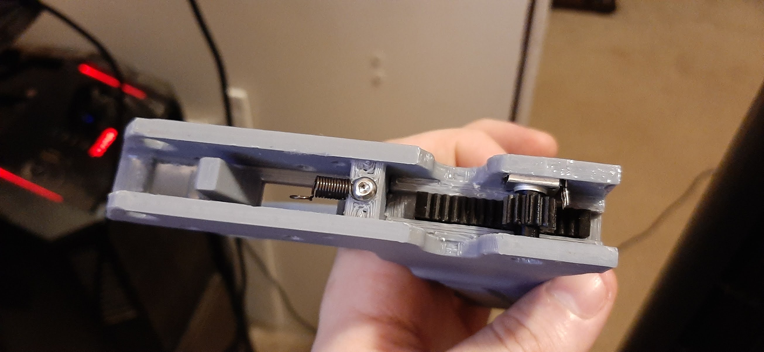
08. CR-10 Heavy-Duty Customizable Print Head


This customizable print head allows you a whole lot of expansion over the stock print head. If you replace the anemic 4010 parts cooling fan with a 5010, or even two 5010's, you should consider this. It also has options for mounting an ANTCLabs BL-Touch, and supports the E3D V6! I've used several different printhead configurations on my S5, and this has been the best so far. You can learn more about this printhead and download the .STL files here!


AND THIS IS TO GO EVEN FURTHER BEYOND! AAAAHHHHHHHHHHHHHHH!!!


09. MGN-12 and MGN-9 Slide Rails


One of the greatest weaknesses of Creality printers is the rubber V-slot wheel bearings they use to guide all of the axiis. Luckily, these can be replaced with CNC machine hardware! These slide rails are meant to move assemblies orders of magnitude heavier than anything on your 3D printer, and they result in much more consistent motions. While the X-axis and Z-axis are largely optional, I found replacing the Y-axis V-slot wheel bearings with MGN-12 slide rails absolutely essential to remove the floppy motion along the Z axis. I recommend purchasing these on Aliexpress (with abundant patience) for the best deal. I suggest Funssor-branded slide rails if you can find them, but everyone seems to have their favorite brand. If you get these, be sure to invest in some PTFE-based lubricant, and buy some spare ball bearings. Do some research on how to maintain them and disassembly/reassemble the carriages, because you may find that some bearings are missing when you get your rails, or some might slip out if you ever take them off of the rails. 


10. Klipper Firmware and Octoprint

This one's a bit of a doozy. First, you'll need a Raspberry Pi - recommended is the 3B+ or newer. Then, install either MainsailOS or OctoPrint, and follow TeachingTech's excellent guide on the Klipper firmware install. Now, before you dive into this project, DO SOME RESEARCH and do not be afraid of having to sift through perhaps dozens of guides from different places to solve problems. This is a very involved overhaul and will push beginners to their limits, but this is the real way to push the S5's performance ceiling above and beyond what is possible with mere hardware adaptations. A key feature of Klipper is the Resonance Compensation and Pressure Advance, which will remove the unavoidable Y-axis banding and rounded corners that plague prints from the CR-10 S5.


Welp, that's the list. Hundreds of hours of R&D over the course of two years of ownership have lead me to this list being the essential upgrades for the CR-10 S5. If you have any suggestions for other parts or general questions, be sure to put it down in the comments!


-Craig, Easterworks

Wednesday, August 12, 2020

The Oni Mask Cover Everyone's Making

Note: You will see a lot of links to products in this build log. These are not sponsored or affiliate links, these are just links to exactly what I used if you decide to closely replicate my process!


I decided it would be fun to 3D print SeanAranda's Oni Cyber Punk Mask. I have a beard that protrudes several inches down from my jaw, so I tend to look silly in the fabric and disposable dust masks everyone's required to wear right now to combat the spread of COVID-19, and I had been thinking of a way to make a mask that I could tuck my beard into so it would look less silly. The Oni mask gained some traction on Reddit's r/3DPrinting subreddit, so I figured it would be a good candidate to try out my ideas.

The first step, naturally, was to print the mask. I printed it on my heavily modified Creality CR-10 S5. I adhered the pieces together using the only tube of Gorilla 2-Part Epoxy in the entire state that wasn't expired. Here are the parameters I used:

  • 0.2mm layer height
  • 0.4mm line width
  • 4 walls
  • 15% gyroid infill
  • AMZ3D PLA

Now, it's worth noting that you shouldn't make masks out of PLA unless you intend to give them some kind of coating. Typically people will use an epoxy resin coat. The reason for this is because PLA is fairly porous and gives bacteria (and viruses!) ample hiding places to avoid disinfectant. I'll be painting the mask with several layers of paint, so I don't have to worry about this issue. I still need to spray it with disinfectant once in a while for safety, though. 

After the epoxy dried, I noticed that there were a lot of gaps in the mask, especially in the "laugh lines" by the nose. I recently bought a 1 lb kit of Aves Apoxie Sculpt, so I figured I would just use that.

I also found during this process that, while Apoxie Sculpt has a 24-hour set time, this can be accelerated to 3 hours if I turn the heated bed on my printer to 60C (140F) and keep the mask in the enclosure. The ambient temperature rises to around 35C (95F), which not only accelerates the chemical reaction to harden the putty, but also significantly lowers the ambient humidity (from around 70% to 25%).

Next up was the first primer pass. I didn't bother doing anything other than removing and sanding notably problematic areas because I wanted to try out hitting a mostly raw print with a high-fill primer to do most of the work for me.

The amount of sanding I had to do after this to get a good, consistent, layer line free finish took about 20 minutes with some 220 grit sandpaper backed with duct tape. That allowed me to get into the awkward areas around the teeth, and the sandpaper held together longer than it would have otherwise. I took the opportunity to normalize areas such as the bottom of the chin. Now it just needed another heavy primer layer and some polishing.

For the polishing process, I typically use 500-100pgt sandpaper with water. However, the nature of this project being "make the processing phase FASTER!", I tried a new idea: a simple Scotch-Brite Heavy Duty Scrub Sponge. I used the rough side (somewhat like a Brillo pad) to rough up the surface and impart some small scratches and features, then used the soft side to polish the surface. The top piece in this image has not yet been hit with the sponge, while the lower piece has. There are still a few areas in this that look "ratty" - some are just paint dust that needs to be wiped away, other areas are things that won't be visible about on the final item and I don't care about.

Now it's time to hit it with the actual paint. I started with two coats of Krylon Fusion All-In-One Hammered Silver. This paint was the best and closest thing I could find to the undercoat color I wanted, though ideally this would not have been an all-in-one paint (these layers tend to be thicker and cover up some detail). I figured, to avoid losing so much detail, I would use half the passes I normally would.

I allowed the paint to sit in direct sunlight for 20 minutes, then hit it with Rustoleum Oil Rubbed Bronze. I wanted this item to look like it was made of metal (obviously), but I felt just going with a straight gunmetal or metallic black top coat would be a bit boring.

I let this sit in the sun for around 40 minutes, then transferred it to my 3D printer enclosure for the same treatment as the Apoxie Sculpt. After a further 20 minutes, the paint was rigid enough that I felt comfortable hitting it with the Scotch-Brite pad. I then went absolutely bat shit with the Scotch-Brite, doing random swirls, aggressive "strikes", and general wear marks.

I'm pretty sure I achieved the look I wanted just with the paint and Scotch-Brite pad. I was going to do a black acrylic wash to make the lines stand out a bit more, but I don't think it's needed now. I decided not to apply a layer of clear coat to encourage a natural wear on the mask surface down to the hammered silver layer.

I put the teeth through the same kind of treatment and installed them into the mouth.

I had to shore up the teeth with some epoxy and Apoxie sculpt because the mounting method the original designer used was somewhat... insufficient. So I needed to make them a bit stronger.

 
I masked the teeth so I could spraypaint the Apoxie sculpt lumps. They aren't very visible from the outside, but I wanted to eliminate their possible visibility at odd angles as much as possible.

With the painting and assembly done, it was now time to figure out the harness, beard concealment, and how this thing is going to interact with a face mask. First, I got the straps around the original mounting points figured out - easy enough.

I used a sewing needle for canvas and some carpet thread to secure the loops. The one part I messed up at in this process was I put the female side of the belt on "backwards", which doesn't really affect function, and you can't notice the mistake unless you're looking very closely and specifically for it.

Now, the upper "cheek bone" strap was a bit awkward. It needed to go up over my ears and secure at the top of my skull.

I had to scratch up the paint and Apoxie sculpt where the straps needed to go so the Gorilla epoxy had some purchase to grab into.


I secured one of the straps around my face, put the mask on, and then masking taped on the strap where it fit best. This shows how I kind of "keyed" the masking tape to the mask (held up about 2mm out of place so you can see the angle of the tape).

After waiting (what felt like) ages for the epoxy to set up, I began also epoxying the "beard hider" into place - the sleeve of an old, black, stretchy undershirt. This was a PAIN - I mixed a small amount of epoxy, spread it out around 2-3cm, held it in place with my fingers until it was tacky enough to hold itself in place, and repeated that process until I'd gone all the way around the jaw. The entire process took around an hour. "5 minute epoxy," HAH!

Somewhere in this cluttered mess is the mask I'm making... Can you find it?

For reference, here is the mask before the "beard hider":

And here is after installing the "beard hider":

It brings together the last 5% to increase the visual effect by a lot more than that.

Welp, this is the part of the build log where I post heavily filtered images to make it look cooler than it probably does:


That's all for now. On to the next thing.

-Craig


Saturday, July 6, 2019

JTW HCC-2A - Further Considerations

I suppose you're never really done until you give up.


Over the past week or so since uploading the HCC-2A, it's gotten a ton of attention (relatively) on Thingiverse, and I've had several people inquire about purchasing a kit from me. The more inquiries I get, the more aspects of the project I become slightly uncomfortable about.

Namely:
-The stock mount, as picture above, is theoretically very fragile. If the kit is dropped, it is likely to break and become unusable.
-The muzzle plate's threading for the mock suppressor is too tight and inconsistent, which makes it very hard to screw the mock suppressor into place, and very easy to pull the threads out.
-The rear receiver and stock mount profiles aren't 100% the same, which I initially hadn't noticed because I was sanding most of the parts.

As such, I've decided to address these problems, and will do so in this post one-by-one.


The Stock Mount

When originally designed, I had intended to print the stock mount out of Taulman 645 Nylon for "production" models. As such, I decided to give this a try.

This is the PLA print of the stock mount, but the Nylon version failed in the same way.

After printing the Nylon version, I put moderate pressure on it with my hand. The end result looked just like the above image. After printing a new design of the stock mount, I tried breaking the old PLA stock mount the same way. It held up SIGNIFICANTLY better. 

This launched me into a six-hour research mission into isotropy in FDM printing. As it turns out, PLA actually is one of the closest FDM filament materials to achieving true isotropy, even if the medium by nature is anisotropic.  

With this part failing in both PLA and Nylon, I decided to re-design the component.

Not pretty, but it's significantly stronger.

While still having the same issues with anisotropy as the buffer tube mounting cylinder, this extra perimeter around the cylinder is much shorter, so more torque can be applied to the furthest point of it. Because of this, the buffer tube is now double-insulated by the mount, and it can withstand a significant amount of force.


The Muzzle Plate

The next issue, then, was the muzzle plate. The solution for this issue is still on-going, but essentially, I'll be relaxing the thread pitch quite a bit on both the muzzle plate and the mock suppressor. Over-aggressive thread pitches in 3D printing tend to not hold up very well - however, the issue here was not the threads themselves sustaining damage, but the cylinder the threads are built into itself separating from the muzzle plate when the mock suppressor is tightened.


The Receiver Profile

Finally, the geometry of the receiver and stock plate needed to be unified. I fixed this by doing what I should have done in the first place, a skill that has become essential in designing consistent, complex mechanical components: Boolean logic operators. In Blender, you can use a Boolean modifier on a set of parts. You can use one of these parts as the "cutting tool" for the other. Essentially, what I did was that I oversized the rear receiver and stock plate, created another object of two large, identical extrusions in the desired profile, and used that as a Boolean cutting tool to enforce an identical profile to the shape of the stock mount and the rear receiver. The screw holes in the rear receiver then needed to be re-aligned to ensure they were centered. After achieving this, the end result was a much more consistent shape over all.


Conclusion

With these issues addressed, the kit is a much more robust, accurate, and interesting option for those with TM Hi-CAPA 5.1's and a desire for a carbine kit. 

I no longer sell these kits to order. It seems everyone expected a fully printed, hand-finished and fitted kit to cost about $5, and they disappeared when seeing $60. Oh well! Go print your own! :-)

Thanks for reading.
-Craig, JTW