Saturday, July 6, 2019

JTW HCC-2A - Further Considerations

I suppose you're never really done until you give up.


Over the past week or so since uploading the HCC-2A, it's gotten a ton of attention (relatively) on Thingiverse, and I've had several people inquire about purchasing a kit from me. The more inquiries I get, the more aspects of the project I become slightly uncomfortable about.

Namely:
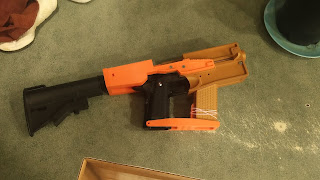
-The stock mount, as picture above, is theoretically very fragile. If the kit is dropped, it is likely to break and become unusable.
-The muzzle plate's threading for the mock suppressor is too tight and inconsistent, which makes it very hard to screw the mock suppressor into place, and very easy to pull the threads out.
-The rear receiver and stock mount profiles aren't 100% the same, which I initially hadn't noticed because I was sanding most of the parts.

As such, I've decided to address these problems, and will do so in this post one-by-one.


The Stock Mount

When originally designed, I had intended to print the stock mount out of Taulman 645 Nylon for "production" models. As such, I decided to give this a try.

This is the PLA print of the stock mount, but the Nylon version failed in the same way.

After printing the Nylon version, I put moderate pressure on it with my hand. The end result looked just like the above image. After printing a new design of the stock mount, I tried breaking the old PLA stock mount the same way. It held up SIGNIFICANTLY better. 

This launched me into a six-hour research mission into isotropy in FDM printing. As it turns out, PLA actually is one of the closest FDM filament materials to achieving true isotropy, even if the medium by nature is anisotropic.  

With this part failing in both PLA and Nylon, I decided to re-design the component.

Not pretty, but it's significantly stronger.

While still having the same issues with anisotropy as the buffer tube mounting cylinder, this extra perimeter around the cylinder is much shorter, so more torque can be applied to the furthest point of it. Because of this, the buffer tube is now double-insulated by the mount, and it can withstand a significant amount of force.


The Muzzle Plate

The next issue, then, was the muzzle plate. The solution for this issue is still on-going, but essentially, I'll be relaxing the thread pitch quite a bit on both the muzzle plate and the mock suppressor. Over-aggressive thread pitches in 3D printing tend to not hold up very well - however, the issue here was not the threads themselves sustaining damage, but the cylinder the threads are built into itself separating from the muzzle plate when the mock suppressor is tightened.


The Receiver Profile

Finally, the geometry of the receiver and stock plate needed to be unified. I fixed this by doing what I should have done in the first place, a skill that has become essential in designing consistent, complex mechanical components: Boolean logic operators. In Blender, you can use a Boolean modifier on a set of parts. You can use one of these parts as the "cutting tool" for the other. Essentially, what I did was that I oversized the rear receiver and stock plate, created another object of two large, identical extrusions in the desired profile, and used that as a Boolean cutting tool to enforce an identical profile to the shape of the stock mount and the rear receiver. The screw holes in the rear receiver then needed to be re-aligned to ensure they were centered. After achieving this, the end result was a much more consistent shape over all.


Conclusion

With these issues addressed, the kit is a much more robust, accurate, and interesting option for those with TM Hi-CAPA 5.1's and a desire for a carbine kit. 

I no longer sell these kits to order. It seems everyone expected a fully printed, hand-finished and fitted kit to cost about $5, and they disappeared when seeing $60. Oh well! Go print your own! :-)

Thanks for reading.
-Craig, JTW

Tuesday, June 25, 2019

Tokyo Marui 5.1 HiCapa 3D-Printed Carbine Kit Build (Part 4 - FINAL, POST-MORTEM)


At long last, this project is at a close. You can download it here: https://www.thingiverse.com/thing:3712294


I originally started the design July 1st, 2017. The first iteration of the files was completed January of 2018. The project was then shelved for quite a while until I picked it back up in November of 2018, and worked endlessly until June 25th of 2019 - today! - to get this final product.

My first impression of the kit is that it is shockingly robust for a completely PLA FDM-printed kit. The one weakness the kit has is the stock tang, and that isn't likely to break unless you put your full weight on it (which you shouldn't do with an airsoft gun in any case).

I ended up threading the muzzle for future accessories (barrel extension, receiver extension). The Action Cam mount on this iteration is also the pre-final - the final version is easier to mount an action camera to.

Old vs. New designs.


Now, for the dead horse segment: the POST-MORTEM.

Successes:
-Aesthetic design is lovely.
-Control group is very easy to access.
-Installation and removal of the airsoft toy is a breeze.
-Feel when using it is awesome.
-AR stock was a good idea.
-Charging handle worked out great after a last-second tweak.

Failures:
-Some dimensions are still too tight and require sanding.
-Full-length optic rail would have been good.
-Longer grip rail would have been good.
-Uses too much hardware (nuts and screws).
-Should have used an original stock design.

In the future, I may come back and address these failures. But for now, the kit is in a form I'm comfortable with releasing publically, and I can't wait to use it at a game.

For those of you who followed along, thanks for checking out my posts here, on Twitter, and of course downloading and trying out the kits on Thingiverse. Thank you to those who held regular correspondence with me about possible ideas for the kit and motivation to continue onward.

For now, I'm off to different projects. After two years off-and-on of developing this kit, I think it's time to handle easier-to-swallow projects for a while.

-Craig


Friday, June 21, 2019

Tokyo Marui 5.1 HiCapa 3D-Printed Carbine Kit Build (Part 3)

The sun is on the horizon for the Hi-CAPA Carbine Project.

After a last few sessions of tweaking, I've now completed the VERY FIRST functional prototype of the V2 kit.

The parts aren't fully hand-finished because this was just a fitment and function prototype.

A few areas need some change. Namely, the slot in the receiver for the accessory rail is slightly too tight, the charging handle binds up slightly toward the rear of the stroke, the reliefs for the manual safeties aren't big enough to let your thumb through, I need to inset a hexagonal slot for the M5 nut the AEG buffer tube screws into, and the grip magazine holder also doesn't quite hang on to magazines.

Otherwise... this was a monumental moment for this project. The airsoft pistol is fully capable of cycling in the kit, and despite the charging handle hanging up sometimes, it's still completely functional - it just needs to be guided forward sometimes. The stock mounting option works great, and I'm now very glad that I went with four M4 screws instead of two, as they're keeping the entire assembly rock solid.

At the suggestion of a Thingiverse user, I've decided I'm going to skip the receiver grip extension for "production" models - most people wouldn't use it anyway, it's not incredibly ergonomic, it complicates printing, and its design still needs to be fleshed out further. The model with this extension is referred to as the "HCC-2B", and the model without is referred to as the "HCC-2A".

After some brief adjustments before the final model, the file will be available for public download on Thingiverse on July 1st, 2019.

See you then.

-Craig

Monday, May 27, 2019

Tokyo Marui 5.1 HiCapa 3D-Printed Carbine Kit Build (Part 2)


Tokyo Marui 5.1 HiCapa 3D-Printed Carbine Kit Build (Part 2)
by Joker Tool Works


Disclaimer: This is NOT a kit for a real firearm! Don't do that! It's illegal and dangerous!


0.1) Introduction

Last time, we modeled the kit, and started printing the minor components. After printing a few mockups, a lot of the parts weren't quite to spec, so a ground-up redesign began. Over the course of nearly a year, the design of the kit is "finished". Let's talk about what's changed, and experiments that took place in between.


An image of the V1 kit. Note that the safety and slide release don't
have much space, and the walls of the receiver piece are very thin.

1) An Experiment

The first of an experimental prototype for improving the kit.

In this test, I made two different variations of the carbine kit. This, the first version, "prototype V0.1," was meant to retain the stock solution and charging handle from the previous model, but was built more carefully around the slide and frame dimensions. This kit printed with some success, but was underwhelming (as it was only meant to "actually work").

This kit is currently available publically to download for free here. Bear in mind that its replacement will soon be uploaded.

The second of the experimental prototype line.

This version of the kit, "Prototype V0.2" kept the same stock solution and general dimensions of V0.1, but added a raised portion on top to facilitate a top-charging handle. While this functioned great, the changes it necessitated for the aesthetic were horrible, and I decided against using this design.

Luckily, after posting the V0.1 to Thingiverse, I received a lot of useful feedback - things such as splitting the receiver into multiple pieces, printing rails directly to the receiver, and ergonomic considerations were mentioned. All of these thoughts have, in one way or another, gone into the official V2 of the carbine kit.

2) Improvements

Ladies and gentlemen, without further ado...

Hi-Capa 5.1 Carbine Kit V2.0, available for free soon.

Version 2.0 of the carbine kit incorporates a bulked-out receiver with better grip detail on the spare magazine holder, an enhanced semi-retained charging handle design, and uses an AR buffer tube and stock rather than the two-bar system of the previous design. The "forward" receiver is divided into five main parts - upper, lower, front, mag grip, and action camera mount. These parts are all readily printable on a 22cm-class 3D printer, making the kit accessible to pretty much anyone with a modern printer, as was the intention. If the action camera is not desired, the resulting hole can be filled with a square peg, which will also be available in the final kit files. With these changes, the kit can reliably be printed out of simple PLA or PLA+ without worry of the kit destroying itself easily.

The only remaining part of this kit that needs to be addressed is the angle of the grip plate. The receiver and grip plate will both have to be printed for me to verify that they're lined up properly, however; if they are, then this kit is absolutely ready for public release. 

A preliminary printing of the new dimensions of the forward receiver has proven very promising. Pictures will be up in part 3.

Saturday, March 2, 2019

Creality CR-10 S5 Enclosure Build (Part 3)

Creality CR-10 S5 Enclosure Build (Part 3)

Skills we'll be using:
-3D Design (Advanced)
-Carpentry (Beginner/Intermediate)

Nearly done now. One more part after this to get it all set up.


With the lid attached, it's finally time to remove the blue cling film from the plexiglass.


It's so large that I, a 6'0", 200lbs man can fit physically inside of it with the lid closed (which I had to do, in order to mend some of the Reflectex around the window after gracefully striking it with my knee in self-defense). The lid, if I had to estimate, has a lifting force requirement of around 80lbs. It can be somewhat uncomfortably opened with one arm. Due to this weight, I have no worries now about the liftgate struts working as intended. I will also likely have to sit inside of the enclosure to install the liftgate struts.

Although I knew this would be a side-effect of the design, in which all corners of the enclosure were sealed, I did not expect the enclosure to be as airtight. Sitting inside of it with the lid on is, in a word, suffocating. The pressure on your ear drums is maddening.

With the enclosure all done, it's time to put the printer in its new home.

Thanks for following along with this journey, thanks to Creality for retweeting my build on Twitter, and thanks to Enotepad for sending me a free spool of filament!

-Craig

Sunday, February 24, 2019

Creality CR-10 S5 Enclosure Build (Part 2)

Creality CR-10 S5 Enclosure Build (Part 2)
by Craig Easter

Skills we'll be using:
-3D Design (Advanced)
-Carpentry (Beginner/Intermediate)

Moving along with the build, I've started putting the insulation in place:


I'm using "Reflectex" aluminum insulation - it kind of feels like bubble wrap with tinfoil on either side. I'm also using Loctite spray adhesive and a staple gun to secure it. The entire inside of the enclosure will be insulated with this material, though it is only really necessary around the bottom of the enclosure. I had to purchase a massive roll of it anyway, and it was cheap, so it's not a big deal.

The lid, which hasn't been photographed for a while, is now painted and has the window attached:


You can still see some of the OSB through the paint, but as I intend on muralizing the exterior, I'm not worried about it.

It is held in with 1/8th" wood cuts held on with wood glue, as well as outdoor silicon sealant around the edges on the interior and exterior sides. While I'm sealing it in the way you might do to waterproof or air seal an environment, this is more to prevent dust from infiltrating around the window. Not pictures is also that the entire interior of the enclosure is now covered in the Reflectex insulation.

I put liftgate struts and mounting pegs on order, but they will take two days to arrive. In the mean time, I'll simply be chucking the door open with a 2x2 beam cut to length. And being very careful not to smack it out of the way while doing so.

With all that sorted, it's finally time to attach the lid to the enclosure and clean up my mess! Once all the adhesives dry, anyway...

Part 3 coming soon.

-Craig

Saturday, February 23, 2019

Creality CR-10 S5 Enclosure Build (Part 1)

Creality CR-10 S5 Enclosure Build (Part 1)
by Craig Easter

Skills we'll be using:
-3D Design (Advanced)
-Carpentry (Beginner/Intermediate)

Recently, I started building the enclosure for my Creality CR-10 S5, here-on referred to as "S5". I needed  a VERY large enclosure to fit the printer. The cabinet in the render above is 1.82m tall.

First, I needed to dissect the 3D model into pieces with accurate dimensions. This whole process took around 4 hours, just making the dimensions more realistic and ensuring everything was square.


Then I needed to determine the amount of space needed by the printer. It ended up needing about 76.2cm of Z-axis clearance, 71cm of X-axis clearance, and an insane 1.09m of Y-axis clearance to provide the space needed to move the 50cm^2 bed's full length of travel. I also wanted interior lighting, an acrylic window, and one or two shelves underneath. It was also the idea to line the entire enclosure interior with aluminum reflective material, both as a fire retardant measure and to enhance the heat trapped in the enclosure.


Beginning with the shelving frame, I spent about 4 hours cutting the wood and manufacturing this (I am not very experienced in carpentry, and this ended up rather shoddy, in my opinion, but it works).

I then needed to tackle the enclosure base frame and lid frame.

 For the entire 2x2 frame, I used wood glue to stiffen the joins. This worked incredibly well.

After adding the shelving, the frame became much more rigid, but I noticed two of the diagonally opposed corners were lifting upward. This would have to be corrected later after adding casters.


After building the frame for the lid, I noticed that the enclosure would be nearly 2.3m tall when the lid was opened, in my garage which has a 2m ceiling clearance. To get around this, I had to trim off the bottom shelf. This lowered the amount of storage the unit provides, but it prevented sacrificing the entire project.


I then began carefully cutting fitted body panels out of OSB. The two wood panels on the lid's sides were surely the most difficult. The front panel is not pictured because it had not yet been attached, and fitment was being checked. Namely, I needed to make sure the lid would slide in and out of the exterior side panels of the enclosure smoothly. There is around 3mm of "play" at the rear of the lid, and almost 1cm of "play" toward the front. While not looking the best, this means the lid will NEVER strike the sides of the enclosure, which was the whole point.


Once locking casters were added, maneuvering the unit around the shop became MUCH easier - however, as previously mentioned, I did have to shim two of the casters to prevent the cabinet from wobbling. I don't believe it's 100% level, but then again, neither is the floor of my garage.

I have begun painting the enclosure using white exterior house paint. Using this kind of paint will make it so that the paint will actually dry despite the cold, damp air present in my neighborhood at this time. It will also leave a very strong, watertight coating around the printer, in the event the enclosure ever needs to be cleaned.

Part 2 will cover installation of the insulation material and prepping the lid for attachment.

Stay tuned.

-Craig